
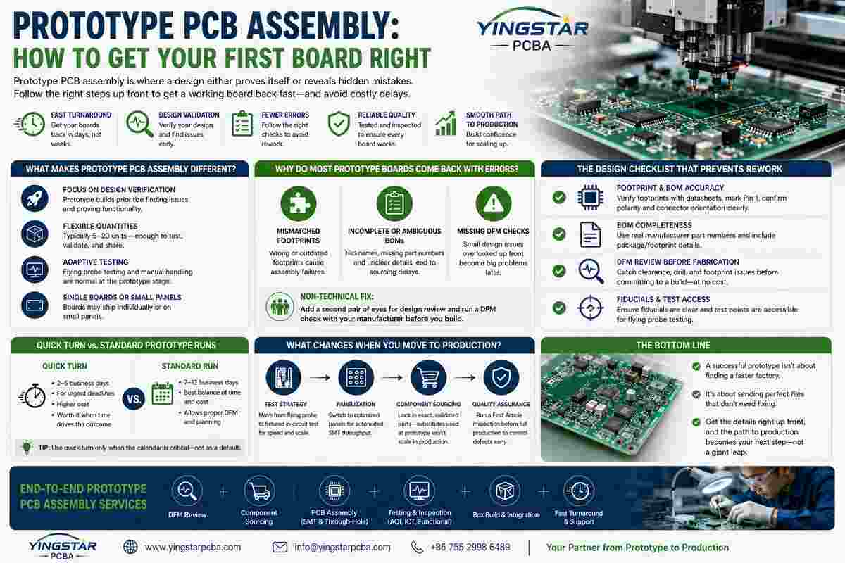
Prototype PCB assembly is where a design either proves itself or reveals the mistakes hiding in the files. Most delays at this stage don’t come from a slow factory — they come from small, preventable errors: a mirrored footprint, a missing polarity mark, a BOM line with a nickname instead of a real part number. Those kinds of errors are exactly what turn a five-day prototype run into a three-week one. This guide covers what determines whether your first board comes back working or needs a redesign.
What Makes Prototype PCB Assembly Different From Production?
Prototype PCB assembly focuses on fast turnaround and design verification, not the lowest per-unit cost. A production run will hardset panelization, in-circuit test fixtures and a fully verified BOM even before the production line is up. A prototype run may ship as single, separated boards or on a small panel, may use a flying probe rather than a bed-of-nails tester and will tolerate some level of manual handling while it is being constructed. That’s not a lesser process — it’s a different one, built around finding problems rather than eliminating variance at scale.
Most shops define a prototype quantity as 5 to 20 units, enough to validate function, run initial reliability checks, and hand a few boards to different team members without ordering a full production panel.
Why Do Most Prototype Boards Come Back With Errors?
The errors cluster in a handful of predictable places: mismatched footprints, incomplete or ambiguous BOMs, and missing design-for-manufacturing checks before files go out. None of these items requires obscure engineering talent to find. They require a non-designer to review the files after work is done because you basically have a tough time finding your own blind spots in design you’ve been working on for several weeks.
There’s a non-technical fix. Add a second pair of eyes for a design review. Run a DFM through your manufacturer before you start laying out panels or assemble your BOM with actual orderable part numbers.
The Design Checklist That Prevents Rework
A few checks catch most prototype delays before they happen.
Footprint and BOM Accuracy
Verify every footprint against the actual component datasheet, not a library part copied from an old project. Clearly mark pin 1 on every IC. Confirm polarity markings on diodes, LEDs, electrolytic and tantalum capacitors, and make connector orientation unambiguous on the silkscreen — the assembler follows what’s printed on the board, not what you remember deciding in the layout tool.
BOM Completeness
List parts by real manufacturer part number, not an internal nickname. Include package/footprint details explicitly. A BOM with vague or missing part numbers is one of the single biggest causes of sourcing delays on a prototype PCB assembly order, because the assembler has to stop and chase down clarification before procurement can even start.
DFM Review Before Fabrication
Send files to your manufacturer for a design-for-manufacturing check before committing to a build. This catches insufficient clearances, unsupported drill sizes, and footprint mismatches at no cost —nothing to fix after fabrication; the same fix means a re-spin and a full turnaround cycle lost.
Fiducials and Test Access
Confirm fiducial markers are present and not obscured by silkscreen, and that test points are accessible for flying probe testing. Skipping this is a quiet way to turn a same-day electrical test into a multi-day workaround.
Quick Turn vs. Standard Prototype Runs: Which Do You Need?
Quick turn PCB assembly compresses a standard 10–12 business day prototype cycle down to days, sometimes hours, for boards facing a hard deadline — a trade show demo, an investor milestone, a critical bug fix. It’s worth paying the premium when speed genuinely determines the outcome. It’s not worth it as a default habit: the same shortcuts that make quick turn fast — skipped DFM review, incomplete BOMs pushed through anyway — are what create expensive failures once a board reaches the field. Reserve quick turn for when the calendar, not curiosity, is driving the order.
What Changes When You Move From Prototype to Production?
The jump from prototype PCB assembly to a real production run isn’t just “order more of the same.” Test strategy shifts from flying probe to fixtured in-circuit test, which pays for its upfront tooling cost through much faster per-unit testing at volume. Panelization moves from single boards to optimized arrays designed for automated SMT throughput. And component sourcing tightens considerably — a prototype might tolerate a substitute part with engineering sign-off; a production run needs the exact validated manufacturer part number locked in, because supply disruptions hit differently at 5,000 units than they do at 10.
Run a first article inspection before authorizing the full production quantity. A defect rate that was an annoyance at prototype scale becomes a real cost problem once it’s multiplied across a production panel.
Conclusion
A clean prototype PCB assembly run isn’t about finding a faster factory — it’s about sending files that don’t need fixing once they arrive. Fix footprint and BOM errors before submission, run a DFM check even if you think nothing is wrong, and set your build speed to your real build time. Getting this discipline right will turn the step from prototyping to production from one big leap into the very next step.